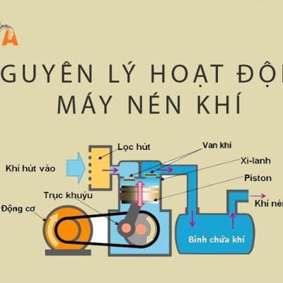
Bơm màng khí nén là một loại máy bơm công nghiệp hoạt động dựa trên nền tảng nguồn năng lượng khí nén. Khí nén được tạo ra từ máy nén khí và được nén vào trong một bình chứa
Trong các ngành công nghiệp, bơm màng không quá xa lạ gì. Tuy nhiên, với những ngành mới chuyển đổi sang sử dụng thì thật khó có thể nhớ được cái tên đó. Cũng khá khó để có thể vận hành thiết bị này nếu không hiểu rõ nó là gì? Nó hoạt động ra sao? Nó dùng để làm gì ?. Bài viết dưới đây sẽ giúp bạn tìm hiểu nguyên lý hoạt động cơ bản của bơm màng để đạt được hiểu quả sử dụng cao nhất
Bơm màng khí nén là một loại máy bơm công nghiệp hoạt động dựa trên nền tảng nguồn năng lượng khí nén. Khí nén được tạo ra từ máy nén khí và được nén vào trong một bình chứa. Do đó, việc sử dụng bơm màng khí nén dễ dàng và an toàn, ít xảy ra sự cố cháy nổ.
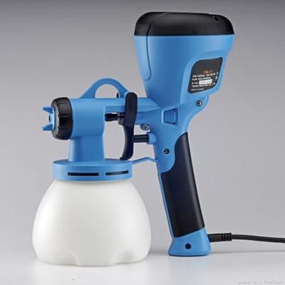
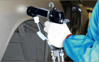
Tuy nhiên trong quá trình sử dụng, cũng cần phải bảo trì thiết bị một cách định kỳ nhằm giảm bớt những hư hỏng do môi trường làm việc hoặc do một sự cố ngoài ý muốn gây ra. Ngoài ra một số bơm màng thường được sử dụng để bơm sơn trong các xưởng gỗ, xưởng gốm sứ,...gara ô tô nên một số người còn gọi là bơm sơn. Cũng đừng lầm tưởng đó là súng phun sơn như dùng trong các ngành công nghiệp khác
* Cách hoạt động của bơm màng
Trước khi biết cách bảo trì máy bơm màng thì ta cần phải biết được nguyên lý hoạt động của máy bơm màng, để tránh xảy ra những sự cố đáng tiếc ngoài ý muốn và làm tốn thời gian, công sức và tiền bạc khi máy bị hư.
Để biết được máy bơm màng hoạt động như thế nào chúng ta cùng nhìn hình bên dưới. Đầu tiên hãy nhìn van khí nén bên cạnh cung cấp khí nén vào buồng chứa bên trái, tạo áp lực đẩy màng bơm sang trái hướng ra ngoài. Dưới áp lực này làm đóng van số 1, mở van số 2, cho phép chất lỏng được bơm đi.
Tiếp theo hình bên dưới đây ta nhìn qua bên van khí nén bên cạnh cung cấp khí nén vào buồng chứa bên trái, tạo áp lực đẩy màng bơm sang trái hướng ra ngoài. Dưới áp lực này làm đóng van số 1, mở van số 2, cho phép chất lỏng được bơm đi. Màng bơm bên phải cũng được di chuyển cùng chiều sang phía bên trái thông qua trục nối. Tạo áp lực chân không đóng van số 4 và mở van số 3, hút chất lỏng vào buồng chứa để chuẩn bị cho chu trình tiếp theo. Kết thúc chu trình 1.
Chúng ta xem tiếp van khí nén bên cạnh cung cấp khí nén vào buồng chứa bên phải, tạo áp lực đẩy màng bơm sang phải hướng ra ngoài. Dưới áp lực này làm đóng van số 3, mở van số 4, cho phép chất lỏng được bơm đi. Màng bơm bên trái cũng được di chuyển cùng chiều sang phía bên phải thông qua trục nối. Tạo áo lực chân không đóng van số 2 và mở van số 1, hút chất lỏng vào buồng chứa để chuẩn bị cho chu trình tiếp theo. Đến đây, kết thúc chu trình 2.
Quá trình bơm được diễn ra tiếp tục qua chu trình số 1.
Đối với sản phẩm 2 đầu vào với 2 loại hóa chất khác nhau, hoạt động của bơm vẫn giống nhau. Hóa chất 1 đi vào qua valve1, hóa chất 2 đi vào van 3. Và được trộn theo tỉ lệ 50/50 ở ngõ ra – tỉ lệ này phụ thuộc vào độ nhớt của hóa chất
Vật liệu và cấu tạo của máy bơm màng rất đa dạng, phù hợp với nhiều hóa chất, môi trường dung dịch khác nhau.